Separators are devices designed to separate and retain petroleum derivatives as well as suspended minerals (sand, sludge) that rainwater and meltwater flowing from any kind of watershed may contain.
OPERATION
Lamella separators separate petroleum derivatives using floatation and sedimentation processes. Wastewater flowing through rainwater drainage system flows into a separator through an inflow chamber which construction enables evening and directing of wastewater flow.
All impurities are separated during multi-layer flow of the wastewater through lamella section. Next, the treated wastewater flows into an outflow chamber. The technology of petroleum derivatives separation used in the device enables also to separate any impurities that can easily form sediment at the bottom of the separation chamber.
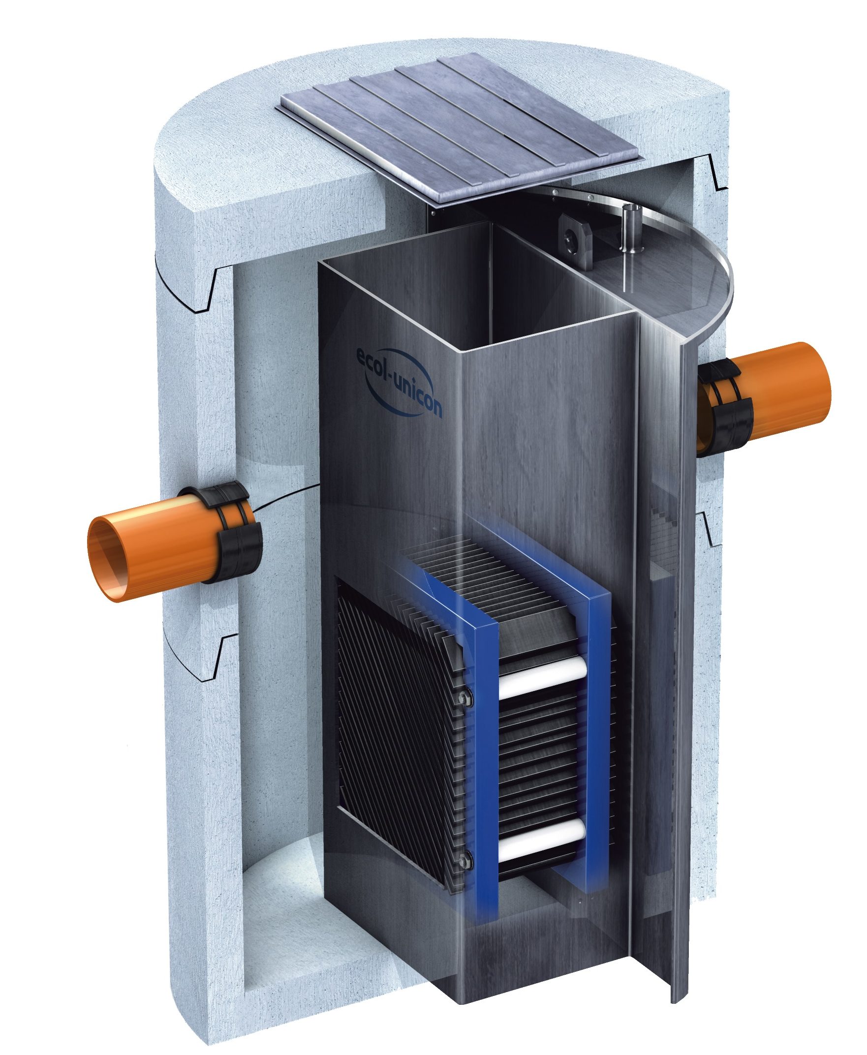 Lamella separator ESL-Z
The lamella section is a replaceable element with two grips for easy taking it out of the separator. Cleaning of the separator can be done from the outside and does not require coming down into the device.
The Environmental Product Declaration (EPD) Type III underscores the supreme ecological standards of our products. As the pioneering company in the water and sanitation industry, Ecol-Unicon ensures products of unmatched quality and commitment to environmental responsibility, thus fulfilling the requirements of EN 15804 and ISO 14025 standards.
APPLICATION, DEPENDING ON SEPARATION TECHNOLOGY USED
It is important to choose the appropriate separation technology for petroleum derivatives depending on watershed type and device working conditions. When choosing the appropriate technology it is important to take the following aspects into consideration:
- watershed size
- protection of the device against potential storm flow
- the amount of suspended solids in wastewater
- separator’s sensitivity (protection zone, prohibited areas, etc.).
Maximum flow coming into a lamella separator and going through the separating section in full is a safe hydraulic load for the device and the impurities held inside it. However, in a separator with by-pass, the flow bigger than nominal is directed into a by-pass pipe. Thus, the by-pass is there only to protect the device from storm flow.
SUSPENDED SOLIDS SEPARATION – COOPERATION OF SEPARATORS WITH A SETTLING TANK
Wasterwater containing high degree of suspended solids should be pretreated in a settling tank. Ecol-Unicon offers petroleum derivatives separators with a settling tank in two configurations:
- with an integrated settling tank ESL-ZH
![]()
- with an integrated settling tank ESL-ZO

- with a settling tank in a separate chamber EOW-2L

The design of a settling tank depends of the location where it is supposed to work, the degree of wastewater pretreatment (rainwater or technological), flows and the estimated amount of suspended solids in inflowing wastewater (Settling Tanks).
Design
Separators have watertight concrete body (chambers of Ø1000–3000 or a separated reservoir chamber) usually does not need extra load. Depending on the separator’s location cast iron or cast iron and concrete manholes classes A15, B125, C250 and D400 are used. In order to adjust the location of the separator slab to ground elevation there is an additional top element used made of concrete rings corresponding to the diameter of the separator’s body. When the sewer system is located deep in the ground, a reduction-slab and a chimney made of ID 1000 rings can be used. The inlet and outlet are located in the axis of the separator. It is also possible to deviate inlet and outlet axes (consult the catalogue for details) as well as connect several inlets.
A separator placed in a concrete tank with foundation on bearing soils up to 10 m below ground level does not need special foundation and does not need static calculations. Normally, excavation is prepared using minimum 10 cm C8/10 (B10) concrete substructure or well-compacted layer of gravel or other course non-cohesive soil. Separators should have gravitation inflow. In case of need for wastewater pumping it is recommended that the pumping station is located after the separator. A separator must be located in a place providing access for a suction vehicle.
A separator’s body can also be made of PE-HD plastic (consult catalogue pages on separators for details).
In order to reduce maintenance costs and improve ecological safety there is a possibility to connect a separator to alarm systems such as sediment level sensors, oil and overflow sensors. Regular monitoring of the device limits the necessity to physically control the device and shortens the reaction time of maintenance teams in case of a failure.
